We are pleased to announce that Alexandr Chernyshev will share with us another great piece of knowledge. He is a renowned expert in the exhibition stand and furniture design management and AVC Programming Lead Developer. You can check out the first article he wrote for us Maximize Your Efficiency in AutoCAD and BricsCAD with the A>V>C> Plugin.
In today’s post, He will share with us, the best and most efficient way of building 3D products using only AutoCAD (or BricsCAD). In order to create beautiful, ready-for-assembly 3D parts, he will be using an unorthodox method of Cutting parts from a Box. This is an intuitive and quick way to sculpt your desired product from scratch in just minutes!
We look forward to sharing Alexandr’s expertise with you and hope it will help you achieve your CAD-related goals.
Problem Introduction
Let’s reconsider how we are taught to model 3D products. Traditional methods, found in textbooks and training videos for CAD programs, typically emphasize starting with a 2D sketch of a single part. From there, the sketch is extruded into the third dimension, and subsequent modifications are made by creating new sketches and additional extrusions. Only after this process, the final product is assembled from these parts. However, it is worth questioning the origins of the initial drawing with dimensions. Who has already designed the entire product? How were the dimensions calculated? Can we be certain that the assembly will work? Why do we need to replicate old drawings in 3D?
In reality, such situations are rare. Let’s consider a more realistic scenario, where in a real company, you are tasked with designing a kitchen or a complex reception desk. It is highly unlikely that you will be provided with the dimensions for all the details. Instead, you might receive an imperfect architectural model, room dimensions, or a few measurements. The remaining dimensions would need to be determined based on your experience and industry standards.
If you are using a parametric program like SolidWorks or Inventor, there is little choice but to start with sketches, then create individual parts, and finally assemble them in 3D. This process can be time-consuming and mentally demanding, as you need to keep the entire assembly in mind.
AutoCAD presents additional challenges, as it lacks 3D parametrization. All part dimensions must be manually calculated. Nevertheless, there is a way to overcome these obstacles. A technique exists that not only eliminates the need for manual calculations but also eliminates the need for sketches in many cases. This alternative approach defies conventional wisdom found in textbooks, and I will now demonstrate it to you.
The Technique: Cut Parts from a 3D Box
For easier understanding, we will follow the creation of a rectangular cabinet. The concept is simple and can be summarised in the following 5 steps:
- Start with modeling the overall shape of the product. Work directly in 3D and create an assembly right away. You can start with any shape not just a simple box.
- Then, using the “_Slice” command, cut out the details from the box as if slicing a sausage with a knife. By adjusting the cutting plane at a distance equal to the material’s thickness from the outer surface of the box, you can easily create the desired detail. No need to name or save it as a separate file in AutoCAD.
- Continue cutting off all other external parts from the box, leaving a stub inside that matches the size and shape of the shelves. This happens effortlessly without any calculations or parameters.
- Adjust the dimensions of the stub to create the necessary gaps and evenly divide it into sections for drawers.
- Proceed to cut off all the internal parts, delete the remnants of the original box, and voila! You now have a complete cabinet model with shelves and drawers.
The best part? You won’t have to input any measurements, except for material thicknesses and gaps. All dimensions of the internal parts are automatically generated without the need for sketches or calculations. In just a matter of seconds, your model is ready! This technique for drawing Complex 3D Parts in AutoCAD works equally well for non-rectangular shapes, including cylindrical and conical surfaces. No more dealing with angles in degrees or recalling trigonometry. It’s time to retrain and save valuable time and effort.
Method Limitations
The proposed method has its limitations. It works exceptionally well for designing furniture, exhibition stands, wooden partitions, stage equipment, podiums, promotional items, plywood frames, and formwork, as well as other flat sheet products. However, when it comes to car design, for example, this technique is not applicable. It’s important to note that we are discussing designing in AutoCAD and BricsCAD, which are lightweight and affordable CAD programs not specifically intended for complex 3D renderings.
While the goal isn’t to completely eliminate 2D sketches, there are scenarios where sketching may not be necessary, especially when the product’s shape is non-rectangular. However, it may still be advantageous to create a sketch and extrude it into 3D.
Keep in mind that in some AutoCAD Clones (ZWCad and GStarCAD) selection of sub-objects is not possible and there for Cut from Box technique cannot be used.
The command set for 3D modeling in AutoCAD is very limited. Although BricsCAD offers interesting commands, they still won’t be enough. Therefore, the use of A>V>C> Plugins becomes essential.
The AVC Slice (ASL) command was created specifically for this modeling technique. It allows for the removal of a flat or curved part with a specified thickness from a solid object. It eliminates the need to adjust the cut plane or surface, requiring only the entry of the desired part’s thickness and indicating the face of the solid to be cut. This command significantly reduces cabinet modeling time from minutes to seconds!
Additional commands include a Multi-Slice, which enables the modeling of simple boxes or columns from the chipboard with a single click and automatically joins the parts at 45-degree angles (miter joint).
The Chop command divides parts into multiple sections, creates gaps, and arranges ribs.
There are also commands for creating part connections (Dado Joint, Cross-piece, Tab & Slot), commands for arranging Fasteners, mass Drilling of holes, Reduce the Weight of parts. By mastering these commands, you will be able to model rapidly and with minimal errors.
Example 1: Creating a simple 3D Cabinet in AutoCAD
You can check out the video below, where the Cut from Box technique is used to create a simple trapezoid cabinet.
Below we will go through each step, explaining the commands used.
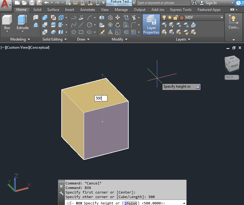
- Create a rectangular box with the dimensions of the cabinet (_BOX command).
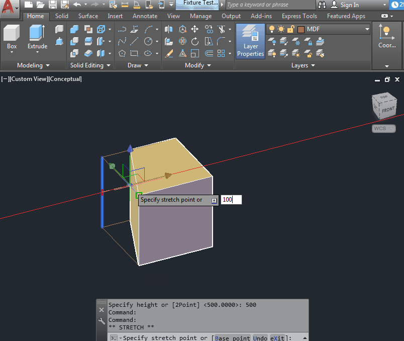
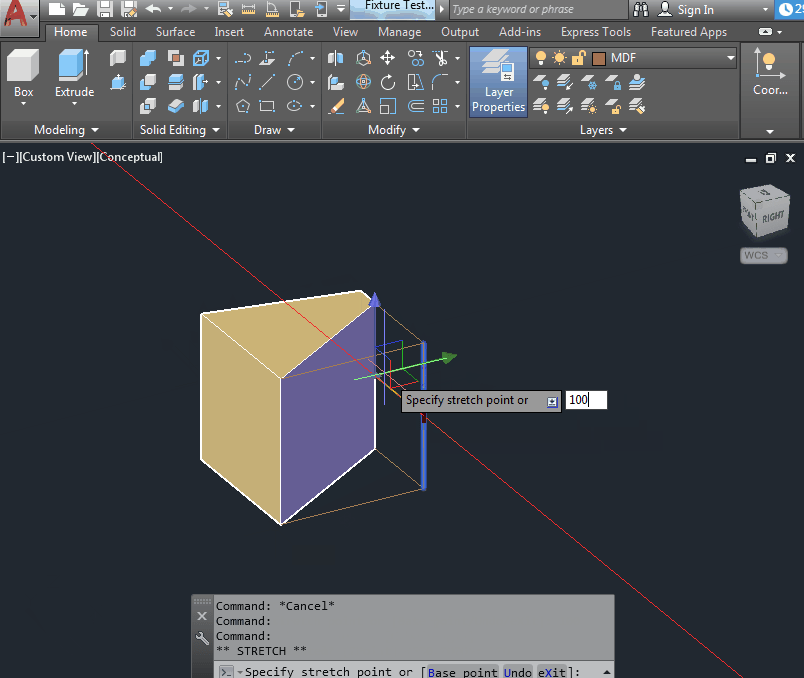
- As the cabinet will be trapezoidal, we need to make the back side shorter. To do this, we will modify the solid by selecting and moving the subobjects.
- Hold down CTRL and click on one of the back vertical edges. The edge will be highlighted in blue. Release CTRL.
- A red grip will appear on the selected edge. It is used to move the selected edge. Just drag in the desired direction and enter the distance. Here you could use the _Move command or the GIZMO arrow.
- Turn the box over to the other side. Instead of using the _Orbit command, you just need to hold the SHIFT key and the middle mouse button and the model will rotate.
- Select and move the second back edge. Now the box will look like a trapezoid.
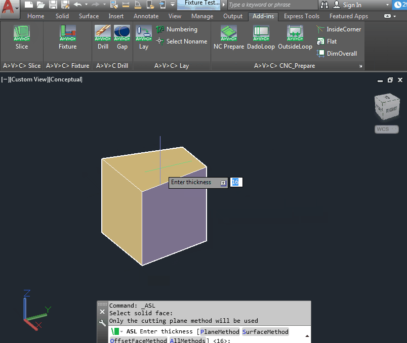
- Next, trigger the _ASL command from the AVC Slice plugin. (You can use regular _Slice, but it is way more inefficient). Click on the top face of the box and enter the thickness of the part (for our example we will enter 16mm.) This gets us a top cover of the cabinet and scarp.
- Rotate the View so you see the bottom of the shape. To do that, you can use the “view cube” at the upper right corner of the AutoCAD screen, or the “chair” in BricsCAD.
- Then, repeat the _ASL command for the bottom part thickness.
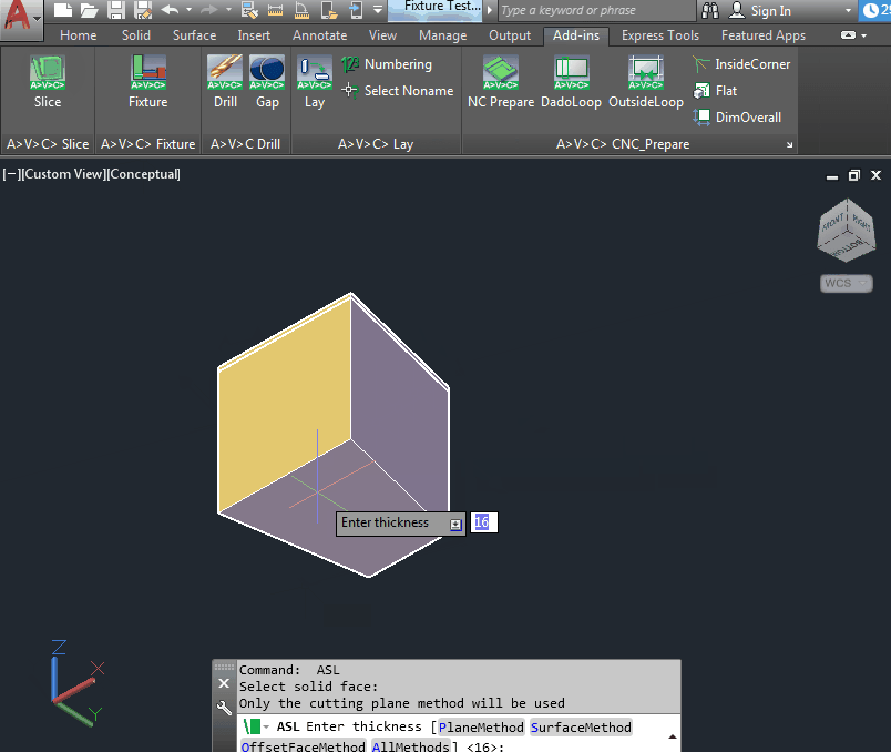
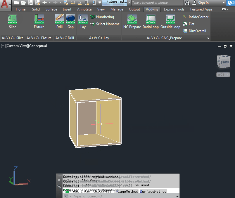
- Continue adding the thickness for all the box walls (sides and back).
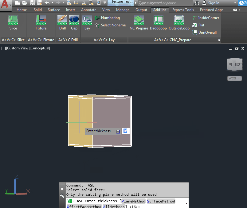
With this, the cabinet frame is ready. 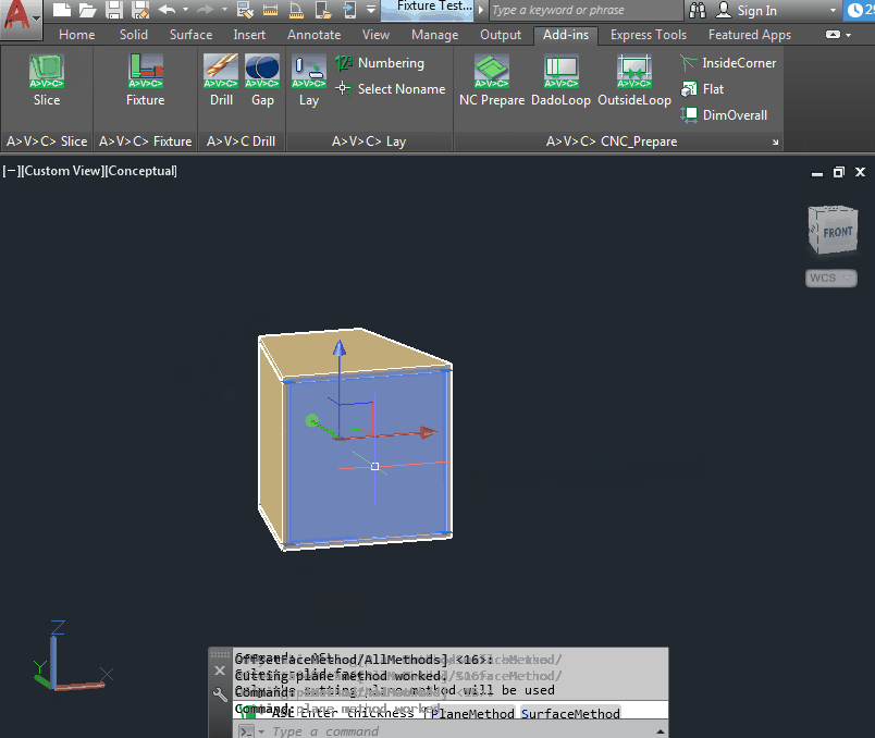
Now you can proceed to make a shelf inside the cabinet. Follow the steps below for easier understanding:
- Select the box that is left between the cut parts and Isolate it using the _Isolate command.
- Cut off the shelf from the box using the _ASL command and _Unisolate the object.
- Move the shelf up/down with the _Move command to place the shelf at the desired location inside the cabinet.
The remaining cut of the original box can be deleted.
In the video above, there are more steps shown, more particularly, the fasteners (minifixes) are placed, all the necessary holes are drilled, the parts are then laid (projected) on the XY plane and finally, layouts are created with viewports for each part.
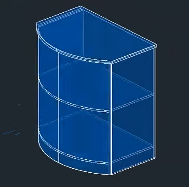
Example 2: Reception desk with rounding
In the second example, we will show you how to create a table with a rounded front wall that can be used as a reception desk on a small exhibition stand.
In the video above, we start with an already created 3D box with a rounded side. This can be easily achieved by either creating a 3D Box and intersecting it with a cylinder, or drawing a polyline being the 2D projection of the cabinet and extending it to a specific height.
The 3D box is then to create the desired reception desk. Find the detailed process in the steps below:
- Cut off the tabletop, for example, 25mm in thickness using the _ASL command.
- Next, create an overhang of the tabletop, by selecting each side and moving it back using the GIZMO Arrows.
- Then, the front part of the stand is cut off. In the example, 4mm is used as the material will be MDF.
Note: The cut-off sequence of the sides is important, you need to always keep in mind how the different parts will be joined/glued together. - Then, the side walls are cut off the same way. The thickness in the example is 16mm.
- After the sides, the bottom of the table is cut off and then raised 100mm to make it more comfortable to use.
- Lastly, the bottom of the desk is copied up 500mm to create a shelf.
The model is ready. Now you can arrange the fasteners or make dadoes for gluing!
Conclusion
Direct modeling in AutoCAD and BricsCAD can offer remarkable speed and convenience with the right approach. “Modeling from the box” is often the fastest and most accurate method for many product types, eliminating the need for calculations and parameters to ensure dimensional consistency. There’s no rush to master complex and costly parametric CAD systems. For simple, non-serial products, parameterization can be more of a hindrance than a benefit.
However, if you require variations of a particular design, automatic parameterization based on pre-existing models is available in BricsCAD.
We hope this guide has been helpful to you, and feel free to check out our other AutoCAD tutorials for more tips and tricks! Or check out A>V>C> AutoCAD Drawing guides.