
Do you need to label your AutoCAD coordinates automatically? If you’re a Civil3D user, you might suggest using C3D, but did you know that AutoCAD can do it too? In fact, there’s an easy way to do it without using any AutoLISPs. In this article, we will create a Dynamic Block that uses Fields and adds automatic coordinates.
A reference Symbol
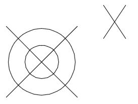
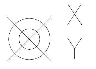
First, create a reference object to use as a reference point. This can be a point, circle, or any symbol you want. Using a point or circle is recommended since you can easily use the point position or circle center.
For our example, we will be using this symbol: 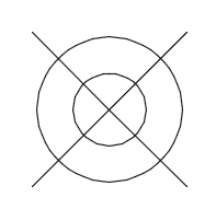
An attribute Definition
Secondly, create an attribute definition, after creating the reference object. In the definition, add a field that can read and display the coordinates of an object. You can do this by following the steps below:
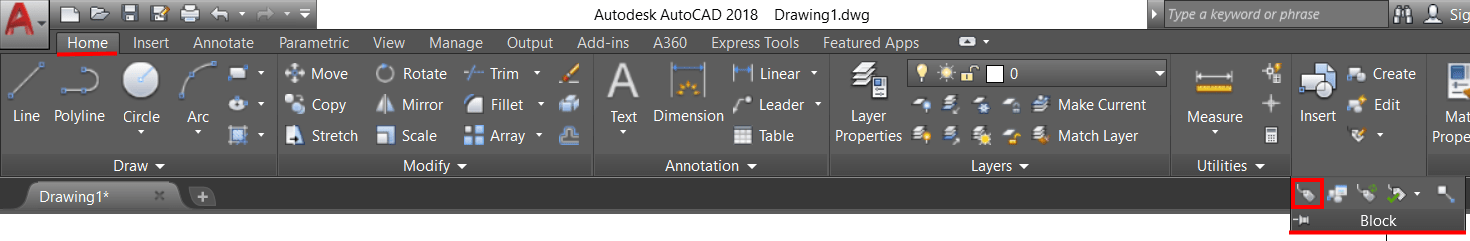
- Click the ATTDEF button under the Block panel on the Home ribbon tab, or type in ATTDEF.
- A window will pop up, there you will define the Attribute.
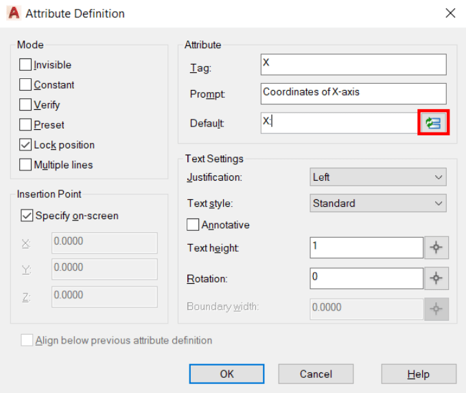
- Under Text Settings, you can also set the Text Style, Justification, etc.
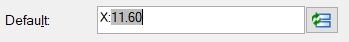
- To define the attribute, fill in the Tag and Prompt as you see fit, and for Default type in X: (for X coordinates) and click on the Field Button.
- A new window will pop up. Here you will define the Field’s properties.
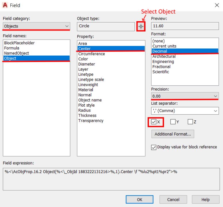
- For Field Category, select Objects from the drop-down menu
- Click on the Select Objects button and select the circle for coordinates.
- For a Property, select Center.
- Then, Select “X” for the coordinates on X-axis and specify Decimal Format with the desired Precision.
- Hit OK, the default value will be now visible.
- Click OK and place the Attribute definition on the drawing.
- Repeat 1-5 steps for Y coordinate, this time, check the Align below the previous attribute definition mark and hit Enter.
Create a Block Object and Use it!
The last step is to create a Block from the objects created above in order to easily add Coordinates in AutoCAD. It is important to define the Center point as the Base Point of the Block.

Note: The grey background of the text shows that it is a Field text, it is not plottable, however, if you still want to get rid of it, type on the command line FIELDDISPLAY and change the value to 0.
Add Leader to the Coordinates Block
To add a leader for the text in the Coordinates Block, follow the steps below:
- Open the Block Editor and draw a polyline leader.
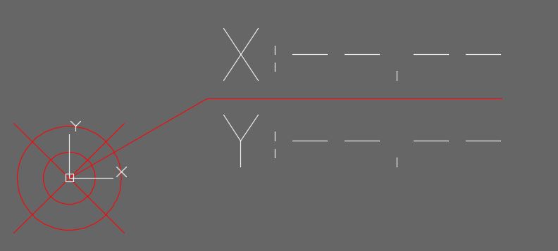
- From the Parameter’s Tab Add the Point Parameter
 to the Leader.
 - Then add a Stretch Action
 to the Point Parameter, selecting both Attributes and the Polyline as shown below:
- Lastly, Close Block Editor and Save the changes.
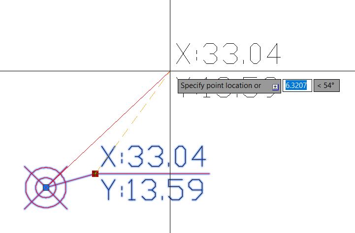
Stretch your label and make it look the way you want it.
Now you know how to label AutoCAD coordinates quickly and efficiently. Give it a try and see how it can simplify your work!
I hope you find this post a value, you can check our other AutoCAD Articles to find even more interesting tips and tricks.
And don’t forget to share this page with your friends and colleagues.