
Alignment objects
Alignment objects are one of the most important parts of Civil 3D drawing. They can represent road centerlines, pipe networks, etc. Creating and defining an alignment is one of the first things we have to do in order to create our roadway, railroad or site design. To create an alignment we usually use the Alignment Layout Tools. Those tools give us great control over the design, providing us with a possibility to use different types of spirals, straight lines, curves and complex combinations of them. We can even create an alignment from Polyline if we have some simple geometry. There is much more information about Alignment Objects in Autodesk’s official site, so I won’t type much about them now.
Alignment stations labels
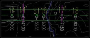
Usually, when we have Alignments for Road Centerlines, for example, we use labels on them for general information like Station’s KM, Station Name or number, Geometry Station Name, Geometry Station KM, etc. Usually, those labels are located in incremental distances and/or at Alignment’s geometry points like Curve-Spiral point (CS) or Spiral-Tangent point (ST) etc. However, some times we want to have labels along custom places (specific KM or Specific place). For example, we have a road and we need a new bridge, we want to put labels on the bridge’s Abutment walls and piers (in the picture they are the Magenta lines). There are three different methods that we can use.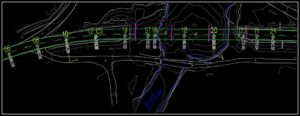
Adding new Major Station Label at one specific KM.
This is a good method if we want to add one or two labels. However, if there are many custom stations that we want to label, this first method will look kind of dull. How does it work:
- First, we have to know the exact Station where we want to place our label. In our example, it would be 0+147.00 (The first Abutment wall of the bridge)
- We open Edit Alignment Labels window by right-clicking over our alignment and choosing Edit Alignment Labels.. from the drop-down menu.
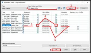
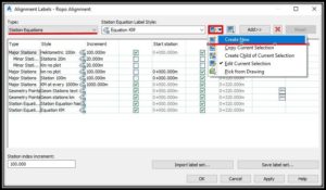
- Here we have to find the label set for our Major stations and ADD it one more time. In mine template, the style is “Station 100m“
- After Adding it we have to set it’s increment to 1m (so we would have label every 1m). After that, we have to uncheck the two boxes before Start and End Station rows, and fill in the Exact Station for both of them. Then we hit OK.
Well, this is it we have our new label at station 0+147.00 as we wanted.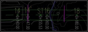
Note: This method my require changing the set up of your Major Station style or even creating an entirely new label style.
Note2: Only this method doesn’t require any setting up on profile’s bands because it uses already existing labels!
Adding Station Equations
The second method is a great solution to our problem! It requires a bit of set up, but after we’ve got our station equation labels ready we can add as many custom labels as we want in seconds!
- First, we have to create a label for Station Equations that will work for us (if we don’t already have one). This can be done by entering Alignment Labels window. Then selecting Station Equations Type and creating new. (in The example I already have a label set but we will go through the process again).
- After creating the label we have to set it up. So now in the Label Set Composer window, we set up our equation label.
- After having our Equation labels set up we just have to add some station equations. This can be done by right-clicking on our Alignment and going to Alignment properties.
- In Alignment properties window under the Station Control tab we can find Station Equations. We just have to click on the Small green plus icon “Add station equations“.
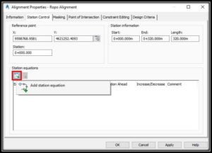
Note: AutoCAD can give you a warning but don’t worry just hit OK. - Now we just have to specify the Station where we want our labels by clicking on the screen.
Note: There is one problem that can occur since station equations are points along alignment where the stationing changes. After adding them as custom labels along with our alignment we have to be very careful not to change alignment’s geometry. Because if we did change it (the geometry before the equation) the equation station will remain the same. The stations after the equation will remain the same, but the stations before the equation will have the new stations.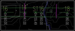
We can easily correct that by copying Row Station Back’s value to Station Ahead. However, if we have a big project we can easily miss the error and then have some big problems!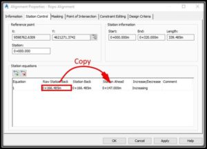
Note2: This method requires setting up into profile band’s options to show our new stations there! You can learn how here: Setting up Custom Station Labels for Profile View in Civil 3D
Adding Sample lines
This is the preferred method by me because there is no danger of messing up the alignment’s stations. And in addition, we have sample lines which can be used for cross sections later on! So how to add custom labels in form of Sample Lines? The process is much like using station equations, we just have to go through these simple steps:
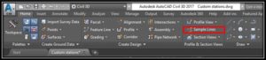
- First, we click on Sample Lines button which is located in Home tab Ribbon.
- Then Civil 3D will ask us to choose an Alignment.
- After choosing the Alignment we have to choose surfaces and corridors, for now, we just hit OK.
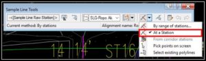
- A small window will pop up called Sample Line Tools. From it, we choose our Sample line Group and method of putting sample lines. In that case, we hit At a Station.
- Now we just have to choose where to put our sample lines by clicking along our Alignment. Civil will ask us for sample line width, but at that point, we don’t care about it so we just hit Enter.
- After placing our sample lines we have to set their labels up, much like setting Station Equation’s labels. Detailed information about setting labels can be found in post Setting up Alignment and Sample Line labels in Civil 3d
That’s it we have our custom Station labels along the Alignment!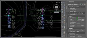
Note: This method requires setting up into profile band’s options to show our new stations there! You can learn how here: Setting up Custom Station Labels for Profile View in Civil 3D