
In this comprehensive guide, we’ll explore how to add a Label to Crossing Alignments with Profile Elevations in AutoCAD Civil 3D, demystifying this necessary tool for civil projects. Whether you’re a seasoned professional navigating complex infrastructure designs or a newcomer to the world of AutoCAD and more precisely Civil 3d, this step-by-step tutorial is tailored to empower you with the skills needed to enhance the speed and efficiency of your designs.
This guide is not just about mastering a tool. It’s about transforming your approach to design by ensuring that your alignments not only meet but exceed precision and compliance standards. Join us as we delve into the functionalities of AutoCAD Civil 3D. Let’s speed up your workflow and make it mistake-proof by learning how to add alignment labels with profile elevations in civil engineering design!
The Concept
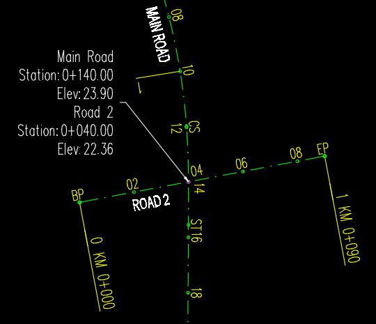
In AutoCAD Civil 3D, the process of adding crossing labels with profile elevations brings a new level of clarity to alignment designs. Picture two alignments intersecting, each with its unique profile. This guide will walk you through the straightforward steps of adding label, showcasing alignment names, stations, and profile elevations. It’s like a visual roadmap, ensuring you not only see where alignments meet but also comprehend the essential data points. Simplify your civil engineering projects with this user-friendly approach, making precision and insight accessible at every intersection.
Label Crossing Alignments with Profile Elevations
To do the trick you first need to have 2 separate alignments with two profile views and profiles. Assuming this is all present, we can start working on creating the said label.
For better understanding the process will be written in easy to follow steps.
- First, add a Station Offset – Fixed Point Alignment label to one of the alignments, right at the intersection point.
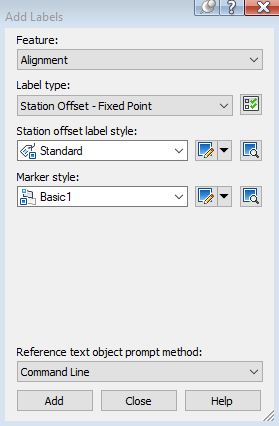
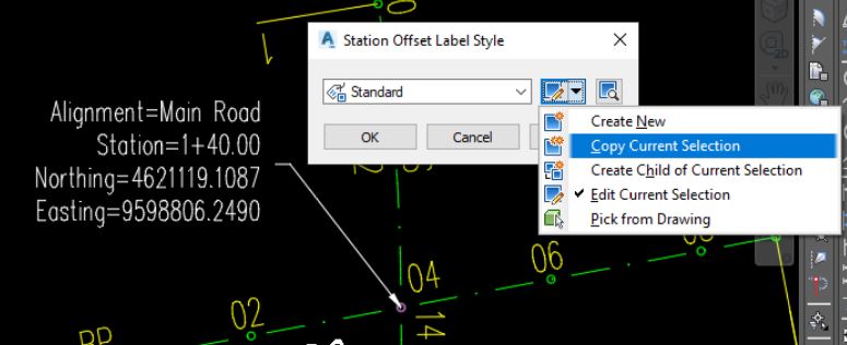
- After adding the Label, right-click on it, and choose Edit Lable Style.
- A window will pop up, there, select Copy Current Selection, to make a copy of the label style and edit it.
- The next step is to set the new Label for Crossing Alignments
- At the Information Tab, under Name, add the name of the new label.
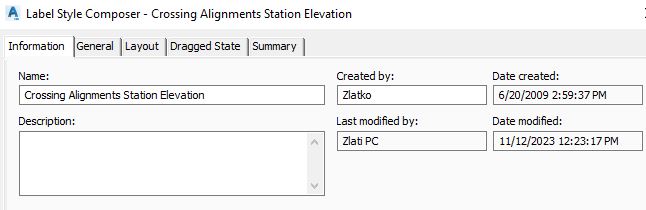
- Then, skip the General tab (there you can set the text style, label visibility, layer, orientation, etc.) and go to the Layout Tab.
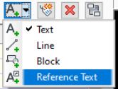
- There, erase the current components and add Reference Text.
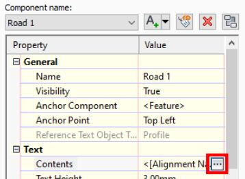
- Add component Name for example Road 1 referencing to 1st alignment and then under Text Contents click on the 3 dots.
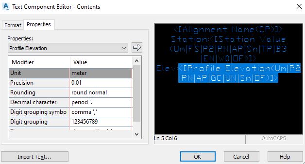
- There, from the drop-down menu on the left side, add the Alignment Name, Station Value, and Profile Elevation.
- Next, click OK, then back on the Layout tab of the Label Style Composer. Here, select Copy Component to make a copy for the second Alignment/Profile data.
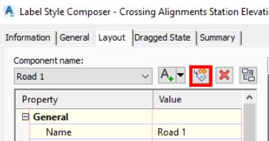
- There, erase the current components and add Reference Text.
- After adding Name to the second component, hit OK to go back to the drawing and see what we did.
- At the Information Tab, under Name, add the name of the new label.
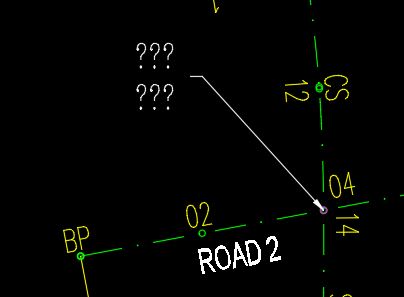
- At that point, you should see a label with question marks like the one in the picture below.
- To fill in the data, select the Label and go to the Properties menu. There, under Reference Text Objects, select the Profiles of the two roads.
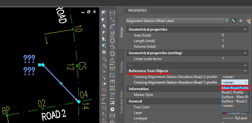
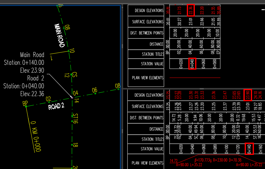
After selecting the reference text objects, the Label at the crossing Alignments with Profile Elevations should be ready to rock and dynamically refresh when the profiles are updated.
In Conclusion: Elevate Your Design Efficiency
Congratulations on mastering the art of adding labels to crossing alignments with profile elevations in AutoCAD Civil 3D! With this newfound skill, you’re well-equipped to enhance the speed and precision of your alignment designs. The seamless integration of labels showcasing alignment names, stations, and profile elevations ensures not just visual clarity but data-rich insights crucial for your civil engineering projects. As you continue to navigate the dynamic landscape of design. Let this guide serve as a cornerstone for efficiency and precision in your AutoCAD Civil 3D workflow.
Hope you find this post useful! You can check our other Civil 3d tips and Tricks!