

Working as a Civil Engineer more particularly doing Road Design, Often I have to work on Road rehabilitation/Reconstruction Projects. When doing design for rehabilitation it is of great importance to use correct point elevations, in order to calculate more accurately Asphalt quantities. Usually, when surveying an Existing road we try to survey at 10-meter sections. However, it is practically impossible to survey a Miles long Road through at exactly 10m (33ft.) sections. This is why we need to place Stations through our Alignment at different increment, exactly where we have surveyed a point. So how do we manage that?
Some programs are able to place stations at surveyed points, but Civil 3D doesn’t allow us this. Today we will go through a method that allows us to do just that!
Stations At COGO Points
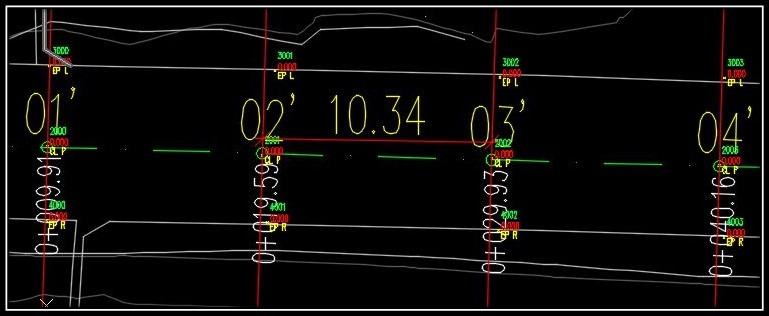
First, let us take a look at our example, we have Points for the Left and Right Edge of pavement and the Centerline.
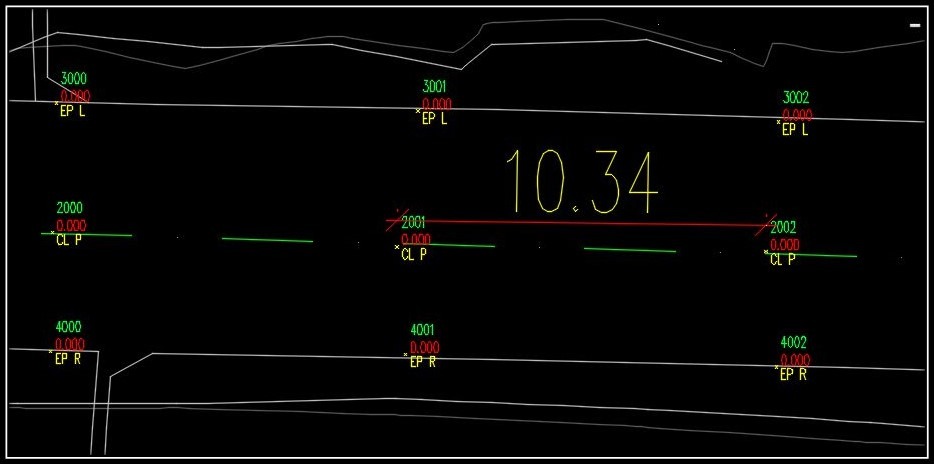
The points are approximately at 10m intervals, now we will add Alignment stations along them. Of course, we can use our Guide for Adding custom stations along Alignment in Civil 3D. but, imagine if we had a thousand points? It would be suicidal time lose for our project. So let’s take a look at the new method that will allow us to Automatically place Stations Along Alignment at Cogo Points.
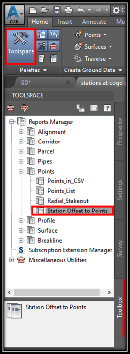
- Open the Toolspace and go to the Toolbox tab.
- Now expand Reports Manager, then Points and double click on Station Offset to Points.
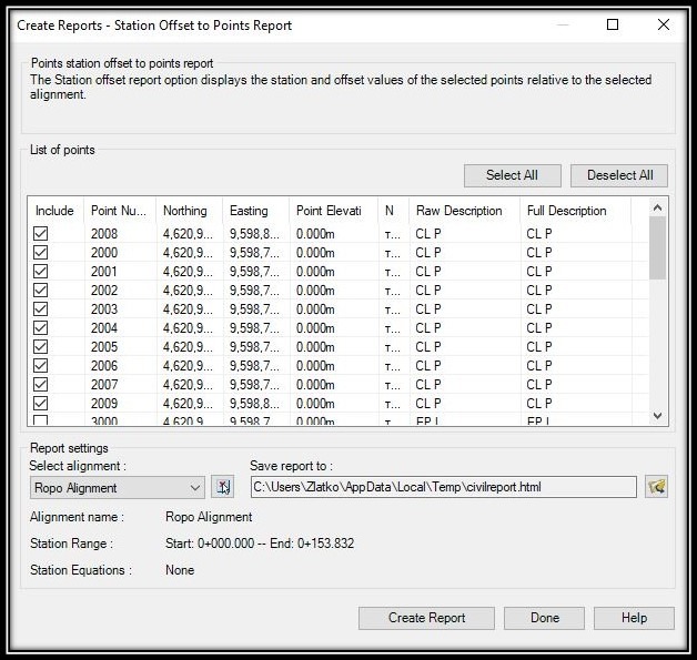
- A window will pop up, there we select the points we want to use for Alignment stations. Then click on Create Report.
- AutoCAD Civil 3D will create an HTML report and will present it into your browser (you can change the format in “save report to“). Now just copy the data in the report and paste it into a Microsoft Excel Spreadsheet (or google sheets).
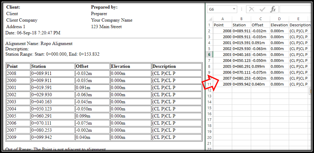
- At this point, we need only the Station Data so we delete everything else and revise the Spreadsheet to look like this:

- Then we save the file in .txt format and open it in the Notepad. There we revise it yet again in order to end up with something like this:
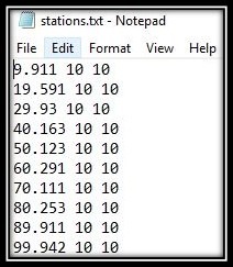
Note: Numbers have to be separated by “a space” - Going back to Civil 3D we Start creating Sample Lines on our Alignment. Now we paste the Number data from the Notepad into the AutoCAD’s Command line.
Now we have Stations exactly where we have Cogo Points!
Set Sample lines to look like Stations
Since I have my sample lines set to look like Alignment Stations and you might not have those set up we will briefly go through the process of setting them. You can find a more detailed explanation of Setting up Alignment and Sample Line Labels in Civil 3d here!
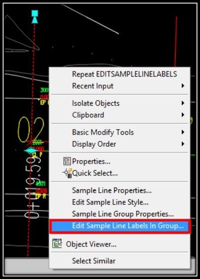
- Go to Edit Sample Line Labels In Group…
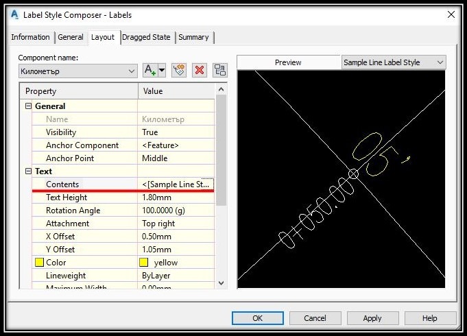
- There create a New Label Style.
- Go to Layout and Add Text Component. Under Contents I have: <[Sample Line Station Value(Ukm|FD|P2|RN|AP|GS|UN|Sn|ORD)]>
To display my station number. However, you can add Station Km or much more.
- After finishing with the Label, Add it to the Sample Line Labels and hit Ok.
You can also turn Sample Line “Line” off in order to hide those lines that go through my Stations.
We will take a look at How to Create a Profile View through Cogo Points in another Post. Stay tuned for that!
If you like the content, don’t forget to subscribe and check out our other Civil 3D related Posts.