
Do you need to extract Points with Elevations from simple Line Objects? Or you need to create a Surface from Line Objects? Well, this was my task today, I needed to create points that have Assigned Elevations and a TIN Surface using Line Objects with Start Z and End Z properties.
We will look at several ways to do that using simple plane AutoCAD or extended functionality of AutoCAD Civil 3D!
Create Points with Elevations from Line Objects using AutoCAD
First, we will look at how to Extract Points with Assigned Elevations from Lines using just an AutoCAD.
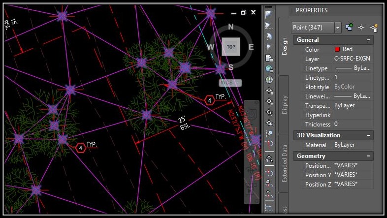
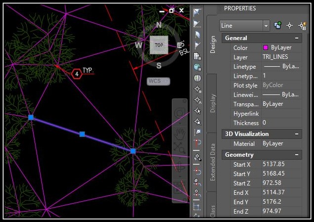
This is the drawing we are going to use, pink lines have assigned Start and End Z properties, that we will use in our Points.
For better understanding, we will use step by step methodology:
- Make sure that your Lines are in separate Layer and isolate them using LAYISO command.
- Type in Command line DATAEXTRACTION to start data extraction tool that will help us extract Coordinates and Z values from Lines.
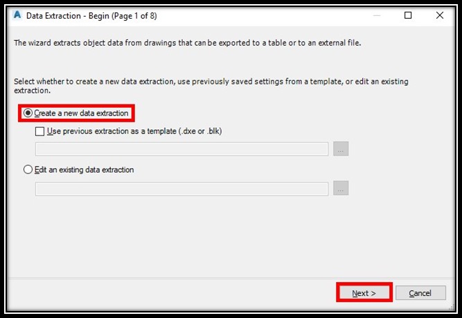
- A window will pop up called Data Extraction. On in mark Create a new data extraction and hit Next.
- AutoCAD will ask you where to save a new file .dxe file, here you just select name and location.
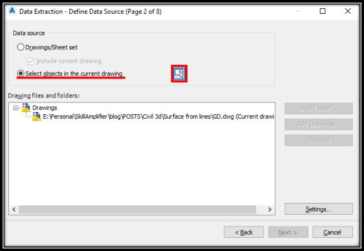
- On page 2 hit Select object in the current drawing and then select all the Line objects you want to extract information from. After selecting click Next.
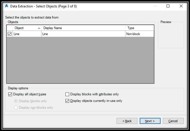
- 3rd page of the Data Extraction tool will show you the types of objects you have selected. Since we selected only Lines, under Objects you will see only Line. Make sure the tick is there and hit Next!
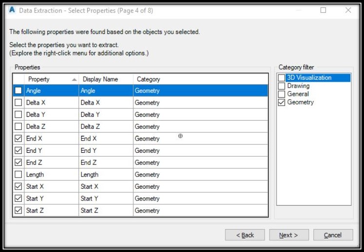
- On the 4th page, is the selection of properties you need to extract. Place ticks only on Start X, End X, Start Y, End Y, Start Z and End Z (which are geometry properties).
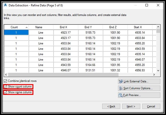
- The 5th page will show the data acquired from those objects. Here I would suggest deselecting Show count column and Show name column since we don’t need those.
- Page 6 is the place for choosing an output. Here select Output data to external file and choose where to save the file
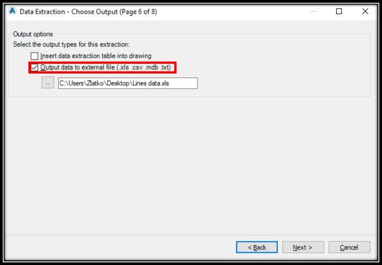
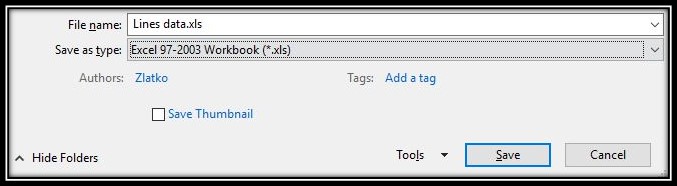
Note: We need data in spreadsheet so make sure file’s extension is .xls - Hit Next and then Finish! Now we have a spreadsheet with data for X, Y and Z of our Lines.
- A window will pop up called Data Extraction. On in mark Create a new data extraction and hit Next.
- At this point, you will end up with Excel file looking like this:
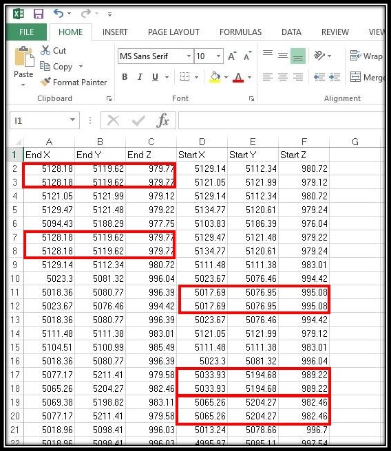
The problem is that we have multiple identical rows, that is because there are several lines that start or end in one point. So we will need to Remove the Duplicates. (Click on the link for more information) - After Formatting the table so that we have X, Y and Z columns it is time to Bring those points back to the Drawing. I am not familiar with creating Lisp routines, so we will use a more primitive method of insertion.
- Before saving the file insert a new column with a specific symbol, for example, * then, save the spreadsheet as Tab Delimited Text by Clicking File > Save As > Choose where to save > Save as Type Tab Delimited.
- Now we have our point data in this format:
5128.18 5119.62 979.77 *
5121.05 5121.99 979.12 *
5129.47 5121.48 979.22 *
…
What we are going to do now is to use Replace function to format the data:
5128.18,5119.62,979.77
5121.05,5121.99,979.12
5129.47,5121.48,979.22
Note: It is very important to have “Space” symbol at the end of every row. This is because we will use simple POINT command to place our points automatically. - The last step is drawing the Points. To do this we will Copy the text with point’s info, go to AutoCAD and start command POINT. Paste the text in the command line.
AutoCAD will draw all the points automatically!
Point Elevations from Lines using AutoCAD Civil 3D
AutoCAD Civil 3D is very powerful software that will help us achieve the same results with fewer steps and some bonuses. This time we will end up with a TIN Surface and Point objects! Let’s go through the steps:
- Firstly we will isolate the Lines using LAYISO Command.
- Secondly, we will create a new TIN Surface from the Prospector Tab.
- Now let’s define the surface using our Line objects. Just go to Definition and then right click on Drawing Objects then Add.
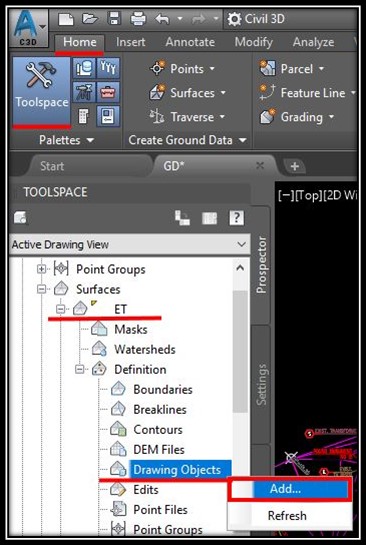
- A window will pop up called Add Points From Drawing Objects. Here under Object type, we select Lines and then hit OK. Now select all the lines.
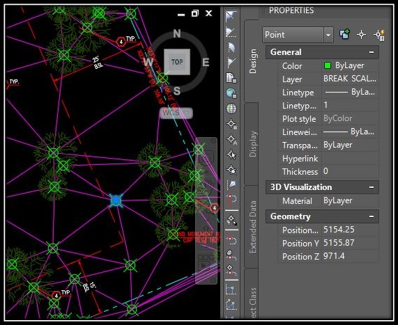
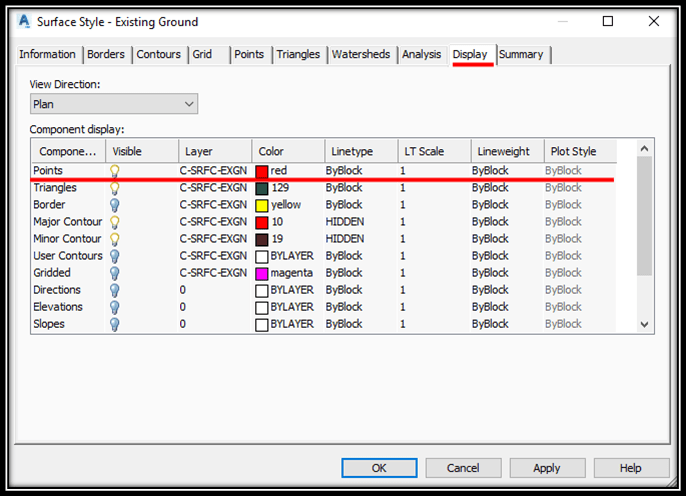
- At this point, we will have a TIN Surface created and defined by the Lines. Now we have to be sure that Points of the surface are displayed. This can be done by right click on the surface (in the Prospector tab) and choosing Edit Surface Style. In the new window under Display, we can see if Points are visible.
- Now, we select our new surface and go to Extract Objects.
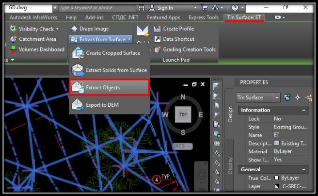
- The Last step is to choose what to Extract. We need Points so check only Points property. And click OK.