AutoCAD Points or Civil 3D COGO Points (What’s new?)

Points are essential objects for Engineers, Land Surveyors and drafters as they represent the coordinates of real objects in the CAD world. AutoCAD gives us this point functionality with its Point objects, however, if we use Civil 3d we will be working with Coordinate Geometry (COGOpoints. Cogo points are very different than AutoCAD Point nodes, let’s see why!

AutoCAD point

To extract information from point objects in the file, we can use DataExtraction .

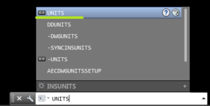
To modify the look of our points we can enter in point style menu by typing DDPTYPE at the command line.

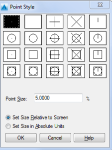
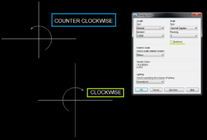
A window will pop up called Point Style, where we can find AutoCAD’s point style suggestions. We can also change the point size, the two options for changing the size are – Set Size Relative to Screen and Set Size in Absolute Units. The names are pretty self-explanatory – if we need points to show up in our drawing with a specific size we can use the Absolute units option. If we are not sure about the scale of the drawing we can use the Relative size.

If we need to place multiple points along an object we can use Measure or Divide commands – This is a really easy way to find coordinates of an object.

The main problem with AutoCAD Point objects is that we can’t add any additional information to them. I’ve seen countless times AutoCAD Point and Text object right next to it. Yes, this may do the trick, but we don’t want to waste much time typing some stuff that we can’t extract later on.
Yes we can create a block with attributes that will have some extractable information, however, if we can use Civil 3D and Coordinate Geometry (COGOpoints we should do so, here is why:

Coordinate Geometry (COGO) points

Cogo Point is a more advanced point – it is a part of the AutoCAD Civil 3D package. Every Cogo Point has its unique number and name. We define points with Description that can contain a wide variety of information.

Cogo Points can be created in different ways:

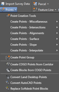
Manual points or by reference – interpolate, intersect, measure, divide, and so on. To do that we have to click on Create Points command located on the Home tab, then choose one of the following:

Create Point – Miscellaneous, Create Point – Intersections, Create Point – Slope, Create Point – Interpolate

We can also create points from Civil 3D objects – like Alignments, Surfaces, and Corridors. This can be done again by clicking on the Create points command and expanding one of the following menus:

Create Point -Alignment, Create Point -Surface, Create COGO Point from Corridor

There is an option to convert AutoCAD or Land Desktop points to Cogo Points.

We can arrange our Cogo Points in Point groups so they will be easier to manipulate.

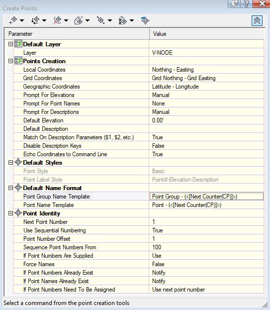
Before creating our Cogo points we can pre-set a lot of settings by hitting on Point Creation Tools. A window called Create Points will pop up. We will see Default Layer, Point Creation, Default Styles, Default Name format, and Point Identity tabs that can be expanded.

  • The default Layer tab is for setting a layer for our new points.
  • Under Points Creation, we can set the position properties of the points along with default elevations and descriptions.
  • Default Styles is used for choosing a Point and Label styles
  • Under Default Name Format we set the counter style and increase for our Points and Point groups
  • The Point Identity tab is mostly used for setting the next Point number

Cogo Point creation tools

Conclusion

In conclusion, I’d like to say that it is really important to understand Coordinate Geometry (COGO) points and start using them because they give us so many more options. They are simple and easy to Create and Use.  The only downside is that they are “big” and heavy objects and if we have lots of them in our drawings AutoCAD Civil 3d can start working slower even on good working stations, so be wise when using them.

Rotate in AutoCAD! Are we doing it Right?

Learn how to use Rotate command as professional!

One of the most common commands we use while working with AutoCAD is Rotate. We are rotating objects like blocks, lines, and text in other words we rotate everything.

Some objects like Text and Mtext for example have their own rotationIt is a great property of the text objects, with it we can easily rotate the text along its base point at a specific angle.
However, it often happens that when we rotate our text it doesn’t look right. Usually, we have to change its base point and then rotate again and this costs us a lot of time. That’s why we use the Rotate command.

Rotate and how to use its full powers!

How do we use the Rotate command? Usually, it goes that way:

  1. Starting the command
  2. We select an object
  3. Click in a random position to select Base Point
  4. Now we start rotating and trying to get that perfect rotation.

Many times we just can’t get it right and have to start over again.

Our suggestions?

I would suggest trying to use different commands for the specific tasks. For example, if we have to rotate, copy, or move several objects it would be smarter to use the command MoCoRo – Move, Copy, and Rotate. All with one! Other times, when we want to rotate several Text objects so they can be more readable we can try using Text Orientation (TORIENT) command. Also, we have to be aware of all the options that the command gives us.

Specify Rotation angle, Copy or use Reference Point.

When we start the command upon rotating you are granted three options: Specify Rotation Angle or [Copy/Reference]:

  • We have an option to click anywhere on the screen and try to guess what is the perfect rotation for us or specify a specific angle.
  • The other option is Copy. When we choose to copy before selecting the rotation angle we will end up with an old object and a new copy of it right where we wanted it.
  • The last Option is Reference, and I’m really excited about it. What it does is giving us the opportunity to rotate an object using a specific reference point. This way we will be sure that our object is placed in the right place. To use we have to go through these simple steps:
    1. Start Rotate command
    2. Select an object we want to rotate.
    3. Specify Base Point
    4. Now when AutoCAD asks us to specify an angle we hit “R” for Reference. Here we can specify the Reference Angle, or just specify again our Base Point.
    5. After selecting the Base Point again we specify the Second – Reference point.
    6. At this point, we can rotate our object by gripping a Reference point and placing it at the place we ideally want.
  • We can also combine several options like rotating an object with a Reference Point and making a Copy of it.

Rotation Direction

The default rotation direction of AutoCAD when entering a specific angle is CounterClockwise. This will work fine most of the time, however in some occasions we may want to rotate an object in the opposite direction.
The easiest way to rotate an object clockwise is to type in “-” before the angle. If we have to rotate several objects clockwise it may be smarter to change Default Rotation Direction.
This can be done by typing Units in the command line. A window will pop up – Drawing Units, there we can check Clockwise under Angle.

How to change Drawing Units in Autocad
units command
Change Default rotation Angle in AutoCAD!
AutoCAD Drawing Units

Note: If you will export coordinates from the drawing, make sure to Uncheck Clockwise. Otherwise, you may end up with the wrong data.

Rotate may be a basic command, but many people don’t use it properly. By remembering these little tips you will accelerate your work, Guaranteed!

.wp-container-core-social-links-is-layout-8e8a235c{flex-wrap:nowrap;justify-content:flex-start;}