
In this article, we are going to look at one very mysterious AutoCAD Object – AutoCAD Splines and try to make working with them easier for us all!
For better understanding, we will be looking at different examples of How to draw Spline and their best uses.
First, what is a Spline in AutoCAD?
When triggered SPLINE, the software creates a smooth curve that passes through or near points we choose on the screen. By default, splines are a series of blended cubic curve segments. They are called non-uniform rational B-splines (NURBS), but we are calling them Splines in short. According to Autodesk’s site, cubic splines most closely represent the line created by using flexible strips that are shaped by weights at data points (About Splines).
Draw SPLINE in AUTOCAD
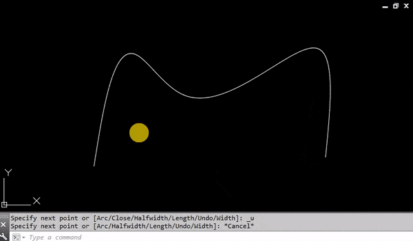
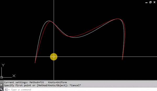
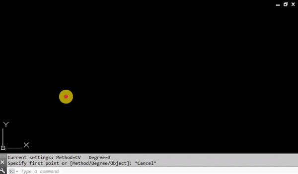
To draw a Spline type on the command line SPL, by default AutoCAD will display Current settings: Method=Fit Knots=Uniform and ask us to Specify first point or [Method/Knots/Object]: Here we can either start drawing, using the current settings or choose a different setting. Let’s see what are the different options we have:
Method
When we select the Method setting, AutoCAD gives us two options Enter spline creation method [Fit/CV] : in other words create spline using Fit Points or using Control Vertices.
Fit
The Fit points method creates blended Cubic curves (degree 3) by specifying fit points that curvature must pass through or if the tolerance value is greater than 0, the spline within the specified tolerance from each specified point.
There are several specific settings for using the Fit method:
- Knots use different computational methods to draw different ways to blend the curves between the fit points. (SPLKNOTS system variable)
- Chord – draws the connecting knots with proportional distances between each pair of fit points.
- Square root – draws the connecting knots with spaces proportional to the square root of the distance between each pair of fit points.
- Uniform – draws the connecting knots with spaces equal regardless the spacing of the fit points.
- Chord – draws the connecting knots with proportional distances between each pair of fit points.
- Start Tangency specifies the tangency of the spline at the start point of the object.
- End Tangency specifies the tangency of the spline at the end point of the object.
- Tolerance specifies the maximum distance by which the blended curves can deviate from the specified fit points.
Note: The tolerance for starting and ending points is always 0
Control Vertices (CV)
The Control Vertices method creates linear (degree 1), quadratic (degree 2), cubic (degree 3), and up to degree 10 splines. (SPLMETHOD system variable)
- Linear Spline (degree 1)
- Quadratic Spline (degree 2)
- Cubic Spline (degree 3)
- Degree 6
Object
When we choose the Object setting, AutoCAD will ask us to select 2D or 3D quadratic or cubic spline-fit Polyline to convert to SPLINE. 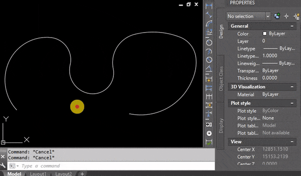
Note: By default, the original polyline will be erased, to save the polyline change the DELOBJ system variable to 0.
If you found this information useful. Don’t forget to check our other AutoCAD Tips for more great Tips and Tricks just like this one!