

AutoCAD is primarily a drawing software, however, there are more, much more uses of the program than just the simple drawing.
One very useful feature is that with the help of AutoCAD we can calculate the second area moment of inertia of a complex section with ease!
Manual calculation of the moment of inertia of any section could be time-consuming. Can you imagine, being on a tight schedule and calculating multiple complex moments of inertia?
Moment of Inertia in a Simple Section
We will start with a simple section and then move on to a more complex one. I hope it would be easier to follow this way.
Now, to make the calculation, we will go through the following steps:
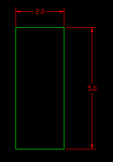
- First, draw the section, in the example, we will use a simple rectangle with sides of 5 and 2 units.
- Secondly, we type on the command line REGION to define a Region object.
- Then, we select all the lines/arcs/polylines that define the section and hit Enter (or Right-Click the mouse)
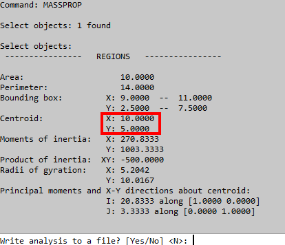
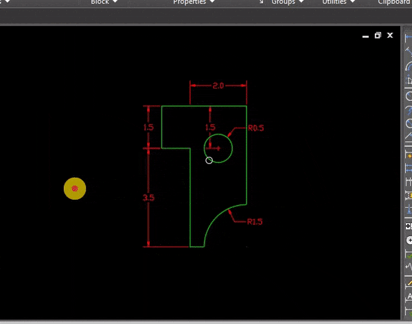
- After the creation of a Region object from our section, we type on the command line MASSPROP and select the Region object.
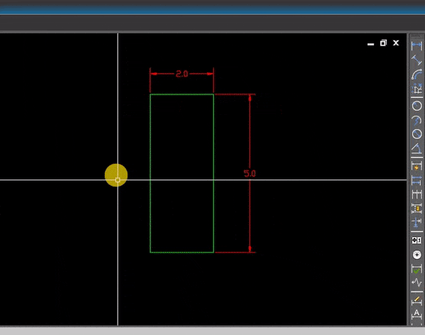
- AutoCAD will automatically provide us some properties of the Section, like Area, Perimeter, coordinates of the Center of the Mass, etc. Now, we move the UCS to the Center of the mass (Centroid)
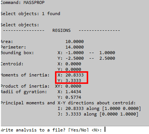
- Lastly, after moving the Coordinate system to the Center of the mass of the section, we trigger MASSPROP again to Find the Moment of Inertia.
Note: The REGION command deletes the original objects after converting them to regions. To prevent it from deleting those set the DELOBJ system variable to 0.
Moment of Inertia in a Hollow Section
Next, we will take a look at how to find the Moment of Inertia in a Complex Section (Hollow asymmetrical section). The steps are pretty much the same with one small exception, excluding the hollow part.
- First, we again draw the Section.
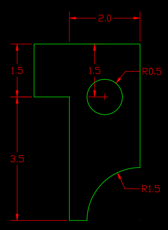
- Then, we start REGION Command.
- Next, we select all objects that define the section, both inner and outer limits. This time we will end up with 2 separate Region objects.
- Now, to combine those objects we will type on the command line SUBTRACT.
- AutoCAD will ask us to Select solids, surfaces, and regions to subtract from, here we select the outer limits of the section and hit Enter
- Then, AutoCAD will ask us to Select objects: Select solids, surfaces, and regions to subtract, here we select the inner object to subtract and hit Enter.
- We’ve ended up with one complex Region Object that represents our section. Now we have to repeat steps 4, 5, and 6 from the previous example.
We type on the command line MASSPROP and select the Region object. - Now, we move the UCS to the Center of the mass (Centroid coordinates)
- Lastly, we trigger MASSPROP again to Find the Moment of Inertia in AutoCAD
If you found this information useful. Don’t forget to check our other AutoCAD Tips for more great Tips and Tricks just like this one!