
Feature lines in AutoCAD Civil 3d are one of the most powerful objects in the software. They are very similar to normal 3d Polylines, but we have an extended number of tools to play with.
Have you ever wondered how to quickly add elevations to a line/polyline/feature line automatically directly from a Surface? Surely I had, in this article we will be looking at exactly that, how to assign elevations to Feature line from Existing Surface.
Method one—creating new feature line object
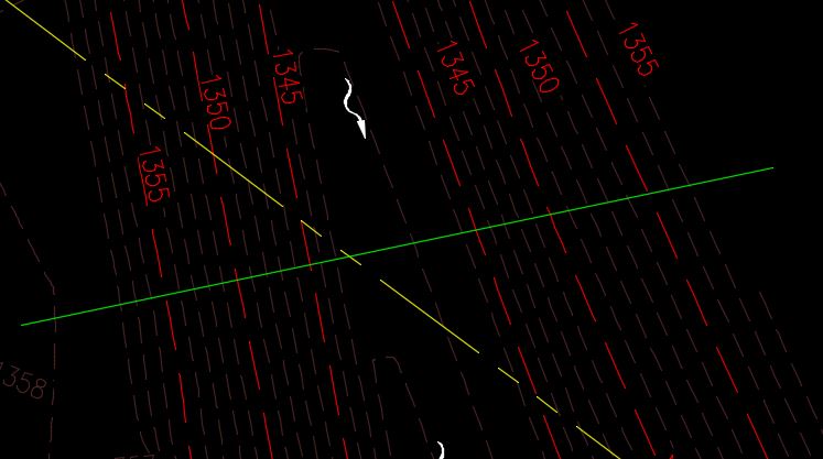
- Decide where do you want your line to be? It can have any shape and can be open or closed.
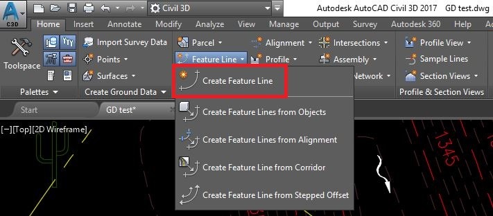
- Click on Feature line and then Create feature line
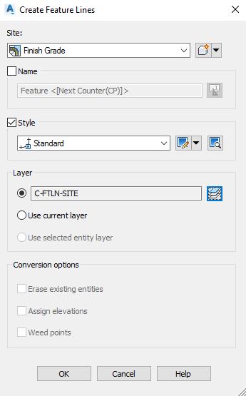
- A window will pop up, here we will set up our feature line.
— At the top you will see Site, for this exercise you can leave it that way.
— Then we see Name, it would be unchecked, you can leave it that way too.
— Next is Layer tab, here I recommend selecting a unique layer which will be used only for our feature lines. In the example we will use “C-FTLN-SITE” layer which stands for Civil-Featureline-Site.
— Lastly, you will see Conversion options, they will be greyed out. You can use them only if we convert an existing object to feature line.
— You are ready to hit, OK.
- Now AutoCAD Civil 3d asks for specific start point, upon choosing one it will ask for elevation, leave it 0 for now, then you will repeat the process until you have the required shape.
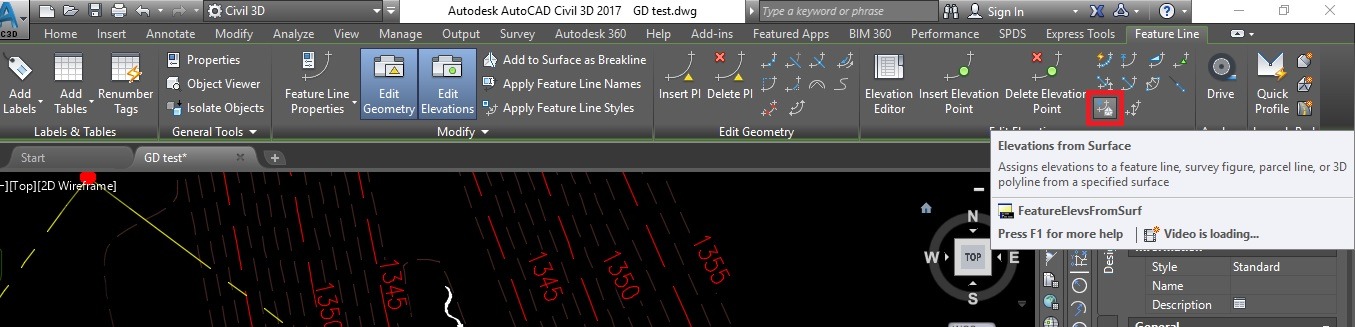
- Now select our new feature line, and you will have a new ribbon – Feature line. Here you can see Elevation from Surface command, just select it.
- A new window will pop up, here you will be asked for two things:
— Choose the surface from which the elevations will come from. We will use ET (existing terrain).
— Insert Intermediate grade break points – check box to insert intermediate grade breaks where the entity crosses surface TIN lines. Elevation points are created at these locations.
Note: If you leave the box unchecked, you will have surface elevations only at feature line’s vertexes.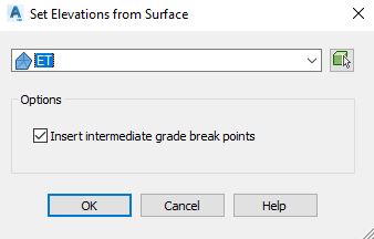
- Click OK, then select the feature line.
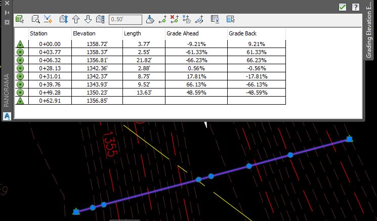
- The feature line is assigned the elevations of the underlying surface.
Method two – create feature line from objects
- Decide where do you want your line to be? It can have any shape and can be open or closed.
- Click on Feature line and then Create feature line from objects
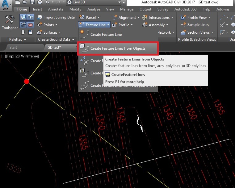
- AutoCAD will ask you to select a line or polyline. Now we will just select our existing polyline.
- A window will pop up, here we will set up our feature line. It will be almost the same as method one.
— At the top you will see Site, for this exercise you can leave it that way.
— Then we see Name, it would be unchecked, you can leave it that way too.
— Next is Layer tab, here I recommend selecting a unique layer which will be used only for our feature lines. In the example we will use “C-FTLN-SITE” layer which stands for Civil-Featureline-Site.
— Lastly you will see Conversion options here we can choose whether to erase existing object or leave it there, we will erase it. To Assign Elevations, we will check that box. Weed points we will leave this unchecked for this exercise.
— You are ready to hit, OK.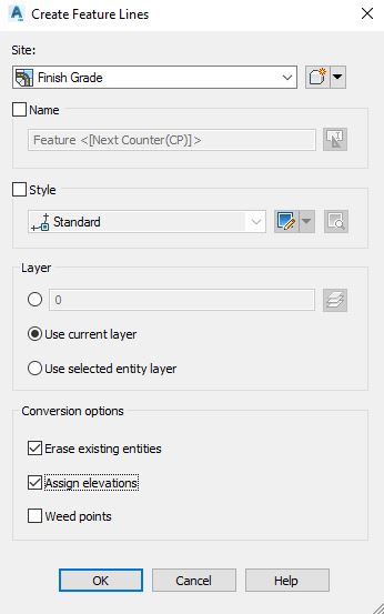
- A new window will pop up, here you will be asked to Assign Elevations, you have two options to set specific elevation for all vertexes or Assign Elevations From Surface.
— Since we want Surface elevations, you will select the surface from which the elevations will come from. We will use ET (existing terrain).
— Insert Intermediate grade break points – check box to insert intermediate grade breaks where the entity crosses surface TIN lines. Elevation points are created at these locations.
Note: If you leave the box unchecked, you will have surface elevations only at feature line’s vertexes.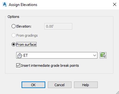
- Click OK, the feature line is assigned the elevations of the underlying surface.
Note: Elevations obtained from the surface are not dynamic.
If you found this information useful. Don’t forget to check our other AutoCAD Tips for more great Tips and Tricks just like this one!