Sometimes contours arrive with no elevations at all. They were traced from a scanned plan, redrawn from a PDF, or the linework was exported flat. They look fine on screen, but every polyline sits at elevation 0, so nothing downstream can use them: no labels, no surface, no profile.
The manual way, and why it hurts
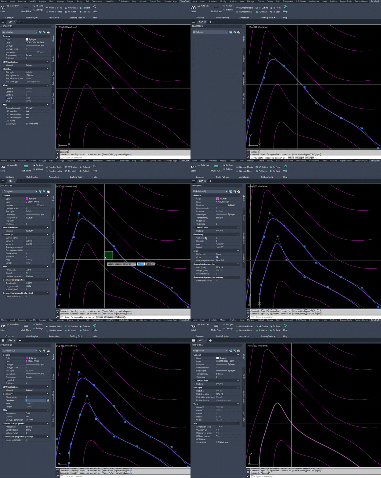
The standard approach is to select one contour, open the Properties palette, type its elevation, then select the next contour and do it again. For lines you edit the start and end Z values. It works, but you are doing the same thing for every contour, you are counting 1400, 1410, 1420 in your head, and one slip in the middle shifts everything after it.
One fence, one run
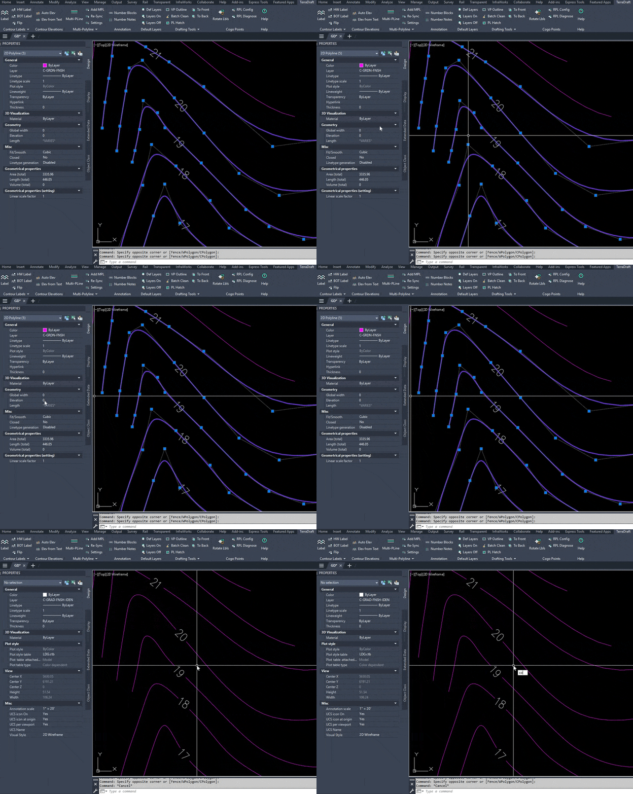
ACE (Auto Contour Elevations) is in both TerraDraft Lite and TerraDraft Pro. You give it a starting elevation and an increment, then draw a fence across the contours. The first object the fence crosses gets the starting elevation, and each next object steps by the increment. Draw the fence in the direction of increasing elevation.
Each crossed polyline gets its Elevation property set. Each line gets both end points moved to that Z. The whole run is one undo group, so a single U reverses it.
Step by step
- Type ACE and press Enter.
- At Starting elevation: type the elevation of the first contour. The prompt shows a default in brackets: 1000 the first time, and afterwards the last value used.
- At Elevation increment: type the step between contours. The default is 10 the first time. A negative number is accepted, for when your fence runs downhill.
- The command line reminds you to draw the fence in the direction of increasing elevation. At Fence first point: click a point outside the first contour.
- At Next fence point (Enter or Esc to finish): click across the remaining contours. Enter or Esc both finish, and the command runs on the points you have picked.
- Read the summary, for example 12 object(s) crossed, 12 elevated.
Tips and common mistakes
- Cross every contour once, in order. If the sequence has a gap, for example a missing contour, the numbering after it is off by one step. Run ACE in sections instead. The order follows what the fence returns, so check the first and last contour in Properties after a run.
- Skipped objects still use up a number. If something on a locked layer or of an unsupported type is crossed, it is skipped and counted in the summary, but the elevation steps on as if it had been set. Read the summary line.
- Supported objects. LWPOLYLINE, 2D polylines (including spline-fit) and LINE. True 3D polylines are skipped and reported, because they carry a Z per vertex. Splines and arcs are not picked by the fence.
- One value per object. ACE sets a single flat elevation for each contour, not a Z per vertex. A contour the fence crosses twice is still one object and gets one value.
- Continuing later. The next value is remembered for the session, so running ACE again continues the sequence. The values are not saved when you restart AutoCAD.
Once the contours have their elevations, labelling is the obvious next step: see how CTT places the labels.
Lite and Pro
ACE is the same in both editions. In Pro there is one extra benefit: the dynamic CTT labels are linked to their contours, so when ACE changes a contour’s elevation those labels update automatically (dynamic contour labels). If your elevations already exist as text on the drawing, Pro also has CONTELTXT, which reads them from the text instead and adds it to the elevations.
Try it
ACE is included in the free edition: download TerraDraft Lite. It was built and tested on AutoCAD 2025 and runs on Windows in full AutoCAD (not LT). If you want the dynamic labels and the extra contour tools, see TerraDraft Pro.
Try it on your own drawing
TerraDraft Lite is free to download.