

In this post, we are going to learn everything about Offset in AutoCAD. We are going to look at what exactly the Offset command means and does, how to use Offset in AutoCAD, the different types of offset distance specification.
Furthermore, we are going to elevate our knowledge even further. Learning tricks like creating Multiple Offsets and Double-side offsets.
Offsetting an object creates a parallel copy of the source at a specific distance in an extremely short time! With the help of Offset, we can create concentric circles and parallel curves as well as parallel rectangles and polylines.
For better understanding, we will go through each case below.
How to Use Offset in AutoCAD
First, let’s start with the basics. To learn how to use Offset in AutoCAD, follow the steps below:
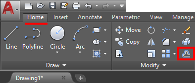
- Offset Icon is located at the Home Ribbon Tab, under Modify. You can also start the command by typing “O” on the command line.
- AutoCAD will ask you to Specify offset distance or [Through/Erase/Layer] <1.0000>:
At this point we can directly set the desired distance for creating a parallel line/arc/circle or choose one of the options:- Through – This option lets you create a parallel object through a point specified on the screen instead of typing in the desired distance.
- Erase – If you choose this option, AutoCAD will ask if you want to erase the source object after the creation of the new parallel one.
- Layer – Lets you choose if you want the new object to be created in the same layer as the source object, or in the layer you have currently active.
- After specifying the offset distance, choose the object you want to offset (create a parallel copy of it).
- AutoCAD will now ask to choose the side to offset, you choose the side relative to the source object by clicking on the screen with the mouse.
Offset a Polyline:
Offset a Circle:
Note: The routine won’t execute fully after the first copy, you can directly select another object or the newly created one to create a new offset copy.
How to create Multiple Offsets in AutoCAD
Often times we need to create more than one parallel copy of our object. For example, if drawing stairs.
AutoCAD gives us the opportunity to create Multiple Offsets with much less effort than selecting and offsetting the object every time. Follow the steps below to learn how to use the Multiple Offset function:
- Start Offset command the usual way as discussed above.
- Specify the desired Offset Distance.
- Select the Object to Offset Multiple Times.
- After selecting the Object AutoCAD Prompts to Specify point on side to offset or [Exit/Multiple/Undo] : This time instead of choosing a Side for the Offset, Select Multiple (hit M key).
- Now, you can choose the side to create the Offset objects.
As you can see, this trick greatly improves the functionality of the Offset command.
Using Extended Offset in AutoCAD
Extended Offset is part of the Express Tools in AutoCAD. It has the advantage to create Multiple Offsets and/or erasing the Original Object using Keyboard shortcuts.
To trigger the Extended Offset type in EXOFFSET on the command line. Or find it on the Express Tools ribbon, under Modify drop-down menu.![]()
The tool works almost the same way as the normal Offset command, to Create Multiple Offsets Press SHIFT key while specifying a Side to Offset.
To Erase the original Object press CTRL Key while specifying a side to Offset.
Extend, Fillet or Champfer Polyline Sigments when Offset
AutoCAD lets us choose how do we want to treat the potential Gaps between Offset Segments of Polylines. If we would like to Extend the parallel lines where they meet, Fillet the distance between them or Champfer it. All this is controlled with a system Variable called OFFSETGAPTYPE.
The default Value of OFFSETGAPTYPE is 0. When chosen, AutoCAD extends line segments to their projected intersections.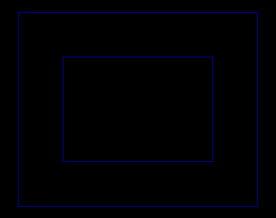
When OFFSETGAPTYPE Value is set to 1, AutoCAD fillets line segments at their projected intersections. The radius of each arc segment is equal to the offset distance.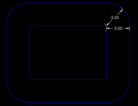
If OFFSETGAPTYPE Value is set to 2, AutoCAD chamfers line segments at their projected intersections. The perpendicular distance from each chamfer to its corresponding vertex on the original object is equal to the offset distance.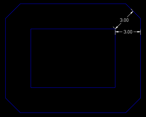
So if, on the other hand, AutoCAD Offset is not working properly and instead of extending the Offset lines is creating Fillet or Chamfer, don’t forget to Check OFFSETGAPTYPE System Variable’s Value!
Double Offset at Once!
We can use an additional Lisp routine created by @LeeMac from www.lee-mac.com. The program works almost the same way as the original Offset Command. The difference is that it will create an offset on both sides of the selected Object. To use the routine follow the steps below:
- Download the Lisp from here.
- Load the Lisp into the AutoCAD.
- To trigger the program type in DOFF on the command line.
- AutoCAD will ask you to Specify offset distance or [Through/Erase/Layer] <1.0000>: here we are able to use the same settings as the Standard Offset command.
- Select the Object to create offset.
AutoCAD does not Offset Polylines, Why?
Sometimes AutoCAD Doesn’t want to offset the polylines we choose to, let’s see why and when that happens. And how to Fix Offset problems.
Check if one of the following issues are present in your case:
- Is there a zero length segment in the Polyline you are trying to Offset?
– To get rid of zero length segments in Polyline you can try using Overkill to get rid of those. - Are you trying to Offset 3D Polyline?
– Quick way to convert 3d Polyline to normal Polyline is to Explode it, selecting all segments and setting their Z geometric values to 0, then Joining those elements again to create normal Polyline. - Nothing happens when Offseting polyline?
– Check if the offset value and the Drawing Units are the same. - Cannot offset on both sides?
– Quite a lot of times AutoCAD doesn’t want to Offset a polyline at one of the sides. The solution I personally use is to offset it the oposite side first and then Offsite the new parralel polyline back by doubling the Offset value.
Hope you find this information useful. Don’t forget to share with friends and colleagues.
For more great AutoCAD Related posts check our Page AutoCAD Tips.