
We already know why Xrefs are so useful but let’s take a deeper look at what additional Extras they offer.
Layers
First and one of my favourite “Extras” is freedom to change reference’s layers in current drawing without affecting the reference drawing.
When we open Layer Properties we see all layers coming from references with xref’s name prefix. In the example we have X- – BS.dwg and our layers have prefix X- -BS|.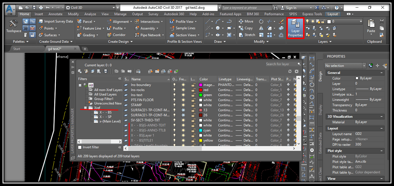
Or if we want to see only layers from references we choose one we are interested in. In the example we will choose x-(Main level).dwg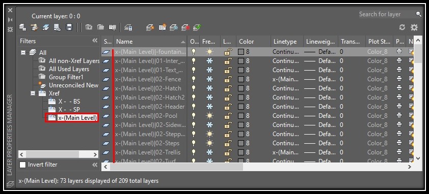
Here are all the layers in that drawing. We will make them color 8 because it works best with our ctb file.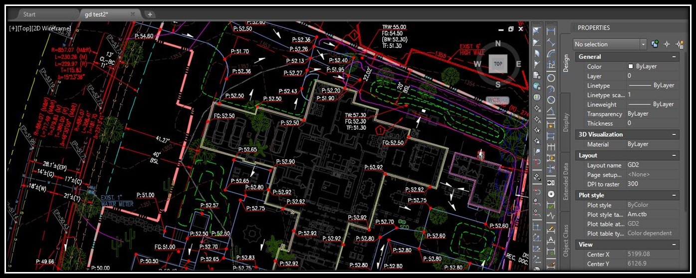
Xref clip
This is also great feature we have with Xrefs. We can create our own clipping boundary to clip references.
To clip an Xref we have two options either select the Xref we want to clip, then right click and select Clip Xref or select the Xref and choose Create Clipping Boundary from the ribbon menu.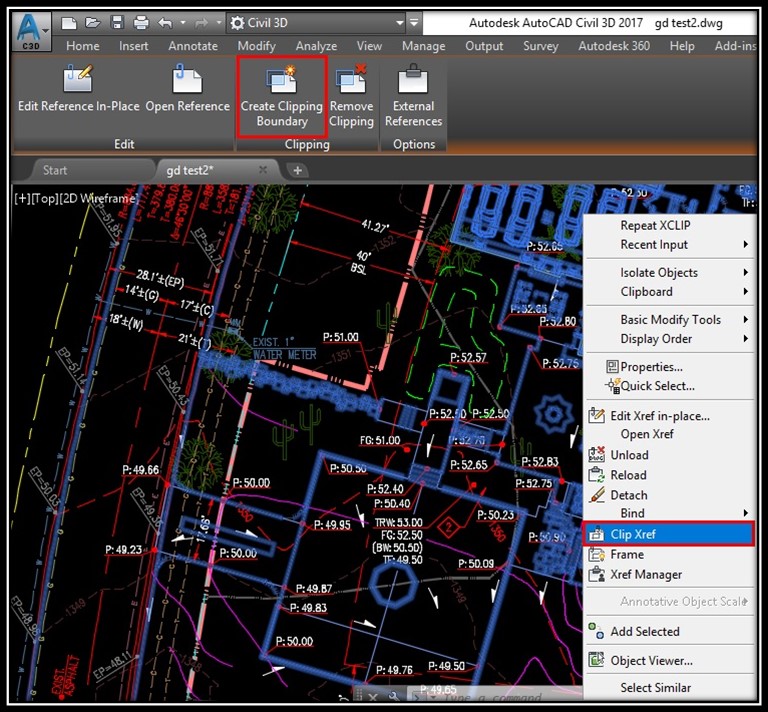
When we select the command we have several options
- On – Turnos on clipping if there is one
- Off – Turns off clipping if there is one
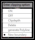
- Clipdepth – Sets the front and back clipping planes on Xref. Objects outside the volume set by boundary and depth are not displayed. We have tree sub options:
Front clip point – Creates a clipping plane passing through and perpendicular to the clipping boundary.
Distance – Creates a clipping plane the specified distance from and parallel to the clipping boundary.
Remove – removes the front and back clipping planes. - Delete – Removes a clipping boundary from the selected Xref. If we want to turn it off temporarily we will use Off option.
- Generate Polyline – Automatically draws a polyline coincident with the clipping boundary. The polyline assumes the current layer, linetype, lineweight, and color settings.
- New Boundary – Here we can create or select new boundary. Upon chosing new boundary we have new 4 options.
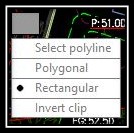
Select Polyline – We can select Polyline already drawn in the drawing.
Polygonal – We can create our own Polygonal boundary
Rectangular – We can create our own Rectangular boundary
Invert Clip – This is very usefull here we can invert the mode of the clipping boundary: objects are clipped either outside the boundary or inside the boundary.
Note: To create new boundary we first have to delete the old one!
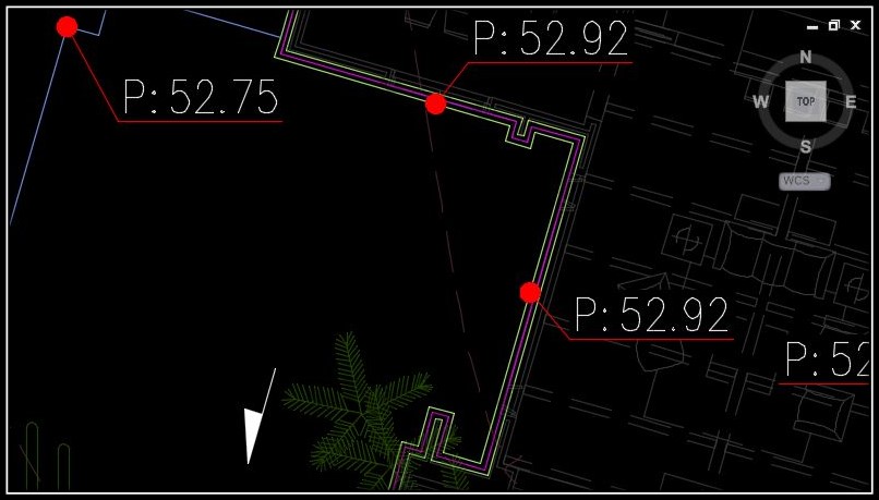
For example we will clip our X- -(Main floor).dwg with our Building outline. We select the Xref, then right click and select Clip Xref, then we choose New Boundary and then Select Polyline.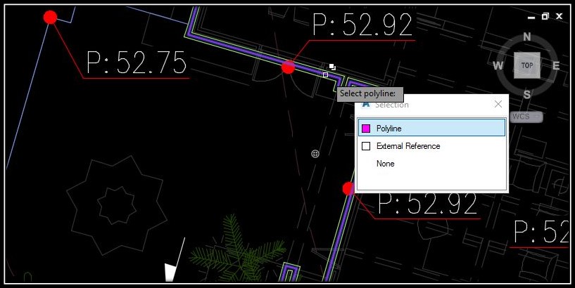
Unload
This is quite basic option which gives us flexibility to unload some of our X-refs 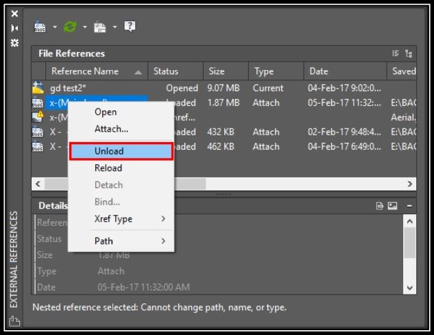 whenever we want that, and then load them back without the need of attaching, scaling and rotating them.
To Unload Xref we have to type “XR” in command lane then choose which Xref to reload, then right click on it and click Unload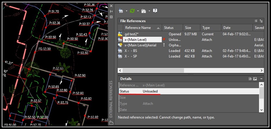
As we can see our Xref’s status is Unloaded, to Reload it just right click it again and click Reload.
Reload
We use Reload usually when we have Unloaded our drawing or if corrections are made to referenced drawing while we are using host drawing.
Detach
Detaches our reference in other words we delete the link between the two drawings.